Thank you Antonio,
I’ve not stop but I don’t want to bore you all with every little bit I do, that’s why I’ve been quiet lately

.
Update……….
I’ve slowed down a bit as I navigate my way around cutting the big aircraft hanger up. I don’t want to get it wrong and I only have a few bits/images to use on how it all worked out. The WEM instructions are extremely vague and I think this quote,
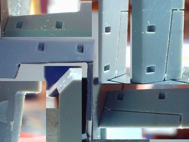
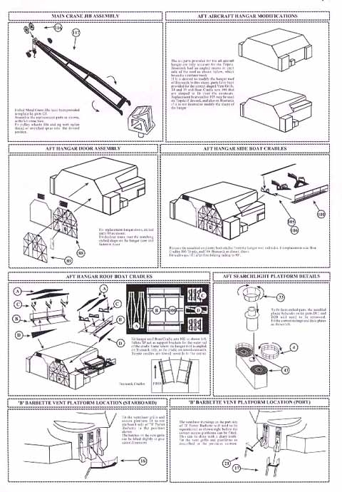
“The kit parts provided (by Tamiya) for the aft aircraft hanger are only accurate for the Tirpitz.
Bismarck had an angled recess in each side of the roof as shown below which housed a ventilator trunk.
If it is desired to modify the hanger roof of Bismarck to this shape, parts have been provided for the correct shape vent grills, 34 and 35 and boat cradle set 106 that are shaped to fit over the contours. Replacement boat cradles 105 may be used on Tirpiz if desired, and also on Bismarck if it is not desired to modify the shape of the hanger.”
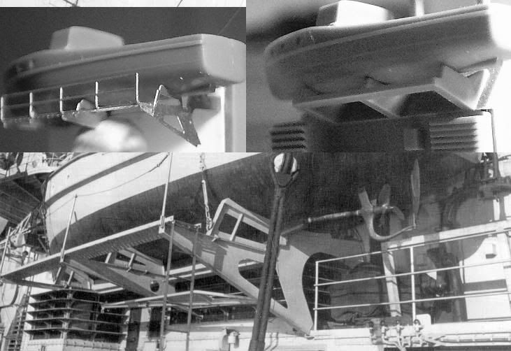
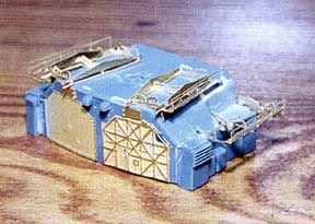
Well if you look at Michael Taylor’s Bismarck hanger, with the WEM parts, you can see that there is little in the way of assistance in negotiating this difficult geometrical option.
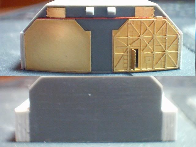
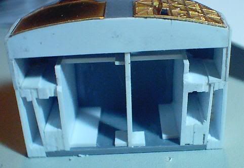
I found that the rear/back is the same width as the searchlight platform part D20. The other cuts are harder to describe and I’ll do that later.
This is the link to the instruction page and as you can see the picture provided changes from the top right-hand corner to the 3 pics of the hanger below.
And the link to the whole thing.
http://www.modelwarships.com/reviews/sh ... smarck.htm
It is always important to remember that aftermarket sets are only as good as the user’s skill. Cutting the hanger up is obviously a difficult job and WEM provide the option of using the Tirpitz cradles (the strongly worded hint in the instructions are there to warn the foolish against wrecking their ship and later trying to blame WEM).
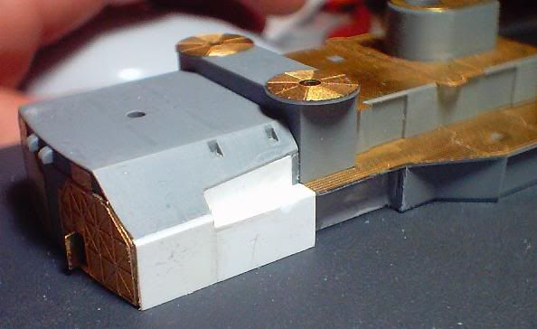
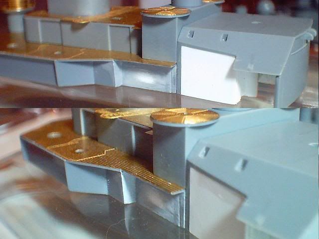
I plan to completely re-work the sidewall on the hanger as it’s not that accurate and even my poor skills can improve the area’s appearance. The parts I removed from the hanger end of D14 are not deep enough and they should cut back in to line up with part D24 directly above and not D20 as I did. I don’t know if I’ll fix it or leave it as is.
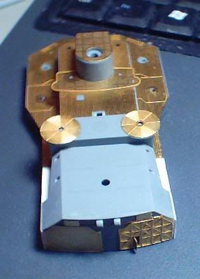
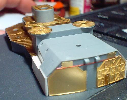
Anyway here is a pic of where I’m at and as I said it’s slowed down due to the need to get the cut up hanger to
A/ line up with the WEM parts.
B/ line up with the kit parts.
C/ line up with the photos and 3D images from around the internet.
All risky stuff as I don’t know at this point which one will dip out, fit wise. Obviously the only real casualty of inaccuracy will have to be option C above.
I’m about to go and do some more on the Bismarck now so I hope to get things rolling faster (got to keep up with the others who are faster than me).
Regards to you all, Steve
I’ve completed all the boat racks assemblies for the big aircraft hanger so it’ll all fall together as soon as I rebuild it. Even with the preview option I know this will be mucked up somehow