Hello,
I wonder which was the way Bismarck detected bearings of enemy radio emissions. I have not been able to see on photos any rotating antenna used as radio direction finder on board, but I believe there actually was such RDF equipment.
Does anyone know how RDF was installed on KM ships ?
hans
Bismarck RDF equipment
Moderator: Bill Jurens
-
hans zurbriggen

- Senior Member
- Posts: 425
- Joined: Sat Dec 21, 2019 8:15 am
-
Herr Nilsson

- Senior Member
- Posts: 1586
- Joined: Thu Oct 21, 2004 11:19 am
- Location: Germany
Re: Bismarck RDF equipment
Goniometer loops
Regards
Marc
"Thank God we blow up and sink more easily." (unknown officer from HMS Norfolk)
Marc
"Thank God we blow up and sink more easily." (unknown officer from HMS Norfolk)
-
hans zurbriggen
- Senior Member
- Posts: 425
- Joined: Sat Dec 21, 2019 8:15 am
Re: Bismarck RDF equipment
Hello Herr Nilsson,
many thanks for confirming there were RDF equipments, however I was unable to locate any 'loop' on Bismarck on available photos.
Actually, there were rotating loops visible on Panzerschiffe (at least until 1938-40, see below from Graf Spee) but removed afterward. No similar loops were ever installed (AFAIK) on Bismarck. Was there a different equipment available for KM by then ?
hans
- AGF_1936_Kiel.jpg (58.76 KiB) Viewed 4105 times
-
marcelo_malara

- Senior Member
- Posts: 1852
- Joined: Sun Oct 02, 2005 11:14 pm
- Location: buenos aires
Re: Bismarck RDF equipment
Hi guys. I would expect such an equipment being installed high in the ship with all around reception, not in front of a steel structure that would need the ship veering to receive in certain bearings.hans zurbriggen wrote: ↑Fri May 19, 2023 10:19 am Hello Herr Nilsson,
many thanks for confirming there were RDF equipments, however I was unable to locate any 'loop' on Bismarck on available photos.
Actually, there were rotating loops visible on Panzerschiffe (at least until 1938-40, see below from Graf Spee) but removed afterward. No similar loops were ever installed (AFAIK) on Bismarck. Was there a different equipment available for KM by then ?
hans
AGF_1936_Kiel.jpg
Regards
-
Herr Nilsson
- Senior Member
- Posts: 1586
- Joined: Thu Oct 21, 2004 11:19 am
- Location: Germany
Re: Bismarck RDF equipment
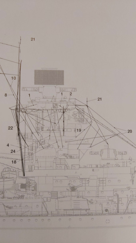
It‘s the wiring around the foretop.
- Quer.jpg (168.39 KiB) Viewed 4082 times
- Längs.jpg (134.04 KiB) Viewed 4082 times
Regards
Marc
"Thank God we blow up and sink more easily." (unknown officer from HMS Norfolk)
Marc
"Thank God we blow up and sink more easily." (unknown officer from HMS Norfolk)
-
marcelo_malara
- Senior Member
- Posts: 1852
- Joined: Sun Oct 02, 2005 11:14 pm
- Location: buenos aires
Re: Bismarck RDF equipment
According to Draminski´s Scharnhorst AOTS, 19 is the RDF antenna.
-
hans zurbriggen
- Senior Member
- Posts: 425
- Joined: Sat Dec 21, 2019 8:15 am
Re: Bismarck RDF equipment
Hello Mr. Nilsson,
many thanks for explanation and detailed photographic evidence: I suppose that, also on older ships, small rotating antennas were replaced by 'large fixed wirings' around the main tower.
However, I still don't see (surely due to my poor technical knowledge) how a fixed cabling (2 dimensional, tough) could determine the bearing of emissions. In a rotating antenna you rotate the antenna until the signal is maximum, then you get (quite precise) bearing. With fixed wiring should you turn ship to determine bearing ?
In this case not a great advance compared with mid 30's rotating antenna, IMHO, but surely KM had some solid reasons to change to this new equipment.
hans
Last edited by hans zurbriggen on Sat May 20, 2023 9:07 am, edited 2 times in total.
-
hans zurbriggen
- Senior Member
- Posts: 425
- Joined: Sat Dec 21, 2019 8:15 am
Re: Bismarck RDF equipment
Hello Mr. Malara,
many thanks for Scharnhorst evidence, pointing to a similar equipment than on Bismarck.
hans
many thanks for Scharnhorst evidence, pointing to a similar equipment than on Bismarck.
there were usually two of these antennas, one fore and one aft. Please see aft installation on board Panzerschiff Admiral Scheer aft of B turret (also this antenna was later removed).I would expect such an equipment being installed high in the ship with all around reception, not in front of a steel structure that would need the ship veering to receive in certain bearings.
hans
- SC-aft-RDF.jpg (40.52 KiB) Viewed 4048 times
-
marcelo_malara
- Senior Member
- Posts: 1852
- Joined: Sun Oct 02, 2005 11:14 pm
- Location: buenos aires
Re: Bismarck RDF equipment
Hi Hans. I would not dare explain its workings, because electronics are beyond my knowledge, but the very first radar, the British Chain Home, did not have rotating antennas. I tried to find in the web how it worked, you have to look to Adcock antenna. But yes, there is a way to RDF with fixed antennas.hans zurbriggen wrote: ↑Sat May 20, 2023 8:53 am Hello Mr. Nilsson,
many thanks for explanation and detailed photographic evidence: I suppose that, also on older ships, small rotating antennas were replaced by 'large fixed wirings' around the main tower.
However, I still don't see (surely due to my poor technical knowledge) how a fixed cabling (2 dimensional, tough) could determine the bearing of emissions. In a rotating antenna you rotate the antenna until the signal is maximum, then you get (quite precise) bearing. With fixed wiring should you turn ship to determine bearing ?
In this case not a great advance compared with mid 30's rotating antenna, IMHO, but surely KM had some solid reasons to change to this new equipment.
hans
Regards
-
hans zurbriggen
- Senior Member
- Posts: 425
- Joined: Sat Dec 21, 2019 8:15 am
Re: Bismarck RDF equipment
Hello Mr. Malara,
However, a 'passive' receiver without rotating antenna can just peak up a signal but it cannot determine emitter bearing, or, in alternative, if receiver is directional (it can receive signals from a certain bearing only, with a receiving 'lobe') then it cannot receive signal emitted out of this 'lobe'.
I suppose KM large 'loops can receive from any direction a radio signal, that would be mazimum when loop is normal (?) to emitter bearing, but, without turning ship, they cannot determine emitter bearing, because there is no way to compare signal strength. That's why I wonder what is reason that brought KM to remove rotating small RDF antennas and replace them with large fixed loops, but I probably miss technical knowledge to understand their functioning.
hans
I understand how an 'active' radar can work without rotating antenna, because emitters have a lobe (e.g. 20° amplitude) and the return echo must be within this lobe (see e.g. Norfolk Type 286M radar during Bismarck chase), thus an approximative bearing. Of course out of the lobe there is no illumination and no target can be acquired by such radar. If you don't have any lobe (emitting on 360°), then the return echo can come from any direction and no bearing info can be obtained.the very first radar, the British Chain Home, did not have rotating antennas.
However, a 'passive' receiver without rotating antenna can just peak up a signal but it cannot determine emitter bearing, or, in alternative, if receiver is directional (it can receive signals from a certain bearing only, with a receiving 'lobe') then it cannot receive signal emitted out of this 'lobe'.
I suppose KM large 'loops can receive from any direction a radio signal, that would be mazimum when loop is normal (?) to emitter bearing, but, without turning ship, they cannot determine emitter bearing, because there is no way to compare signal strength. That's why I wonder what is reason that brought KM to remove rotating small RDF antennas and replace them with large fixed loops, but I probably miss technical knowledge to understand their functioning.
hans
-
Herr Nilsson
- Senior Member
- Posts: 1586
- Joined: Thu Oct 21, 2004 11:19 am
- Location: Germany
Re: Bismarck RDF equipment
The two antenna "loops" are at right angles to each other. Each of them is connected to a coil. These two coils are at right angles to each other as well. One of these coins is slightly smaller and inside the other one. So they are building an axially symmetrical kind of "frame". Inside of this "frame" is a rotatable third coil with its axis running through the intersections of the two other coils.
To detect the bearing the inner coil was rotated. The position of the lowest sound volume indicated the direction of the signal source.
To detect the bearing the inner coil was rotated. The position of the lowest sound volume indicated the direction of the signal source.
Regards
Marc
"Thank God we blow up and sink more easily." (unknown officer from HMS Norfolk)
Marc
"Thank God we blow up and sink more easily." (unknown officer from HMS Norfolk)
-
hans zurbriggen
- Senior Member
- Posts: 425
- Joined: Sat Dec 21, 2019 8:15 am
Re: Bismarck RDF equipment
Hello Mr. Nilsson,
many thanks again for your explanation. Despite not being fully able to appreciate the technicality you describe, I understand that, thanks to two separate loops at 90° angle, the fixed antenna 'loops' devices are able to detect the bearing of the emitting source, without turning the ship.
It makes sense then that KM replaced the small rotating antennas with these devices, possibly improving performances.
hans
-
marcelo_malara
- Senior Member
- Posts: 1852
- Joined: Sun Oct 02, 2005 11:14 pm
- Location: buenos aires
Re: Bismarck RDF equipment
Hello Hans. I believe the all thing is related to the phase of the incoming signal If you have two receiving sensors the phases sensed by the two differ by an amount related to the angle between the signal and the sensors. The same principle was applied to the GHG passive array.hans zurbriggen wrote: ↑Sun May 21, 2023 8:11 am Hello Mr. Malara,
I understand how an 'active' radar can work without rotating antenna, because emitters have a lobe (e.g. 20° amplitude) and the return echo must be within this lobe (see e.g. Norfolk Type 286M radar during Bismarck chase), thus an approximative bearing. Of course out of the lobe there is no illumination and no target can be acquired by such radar. If you don't have any lobe (emitting on 360°), then the return echo can come from any direction and no bearing info can be obtained.the very first radar, the British Chain Home, did not have rotating antennas.
However, a 'passive' receiver without rotating antenna can just peak up a signal but it cannot determine emitter bearing, or, in alternative, if receiver is directional (it can receive signals from a certain bearing only, with a receiving 'lobe') then it cannot receive signal emitted out of this 'lobe'.
I suppose KM large 'loops can receive from any direction a radio signal, that would be mazimum when loop is normal (?) to emitter bearing, but, without turning ship, they cannot determine emitter bearing, because there is no way to compare signal strength. That's why I wonder what is reason that brought KM to remove rotating small RDF antennas and replace them with large fixed loops, but I probably miss technical knowledge to understand their functioning.
hans
Regards
Re: Bismarck RDF equipment
Battleships originally did not use radar, they used aircraft only. Bismarck had floatplane which could have done this and ESM wouldn't be needed. I'm unsure if there are any accounts of the float plane being used.
Mark
Mark
-
hans zurbriggen
- Senior Member
- Posts: 425
- Joined: Sat Dec 21, 2019 8:15 am
Re: Bismarck RDF equipment
Hello Mr. Malara,
yes, you are most probably right: I think phases are involved. Too much technical for me, but I feel that 2 large loops are capable of determining radio emissions bearing.
I think also 'diamond' equipment (e.g. on aft mast of Prince of Wales) is not rotating, but it was able (thanks to 2 small loops at 90°) to determine Suffolk bearings during Bismarck chase.
Curious to understand what was advantage that persuaded KM to remove small rotating single antennas, replacing them with such large loops instead of small 'diamonds' like on British ships though (sensitivity ? speed in determining bearing ? other ?)
hans